Simulation
The Simulate workspace runs three kinds of study on one solid body. Choose the study at the left of the toolbar or at the top of the panel:
- Static: stress and deflection under loads. Use it to find weak spots and check that a part is strong enough.
- Modal: the part's natural frequencies and how it vibrates at each one.
- Generative: lets the computer remove the material that carries no load, to show you a lighter, stiffer shape.
- Thermal: the temperatures a part settles at with heat sources, fixed temperatures and cooling.
Setting up a study
- Give the body a physical material in the Design workspace (Modify ▸ Physical Material). The material sets the stiffness (Young's modulus and Poisson's ratio) and the strength used for the safety factor.
- Open Simulate from the workspace switch at the top of the window and choose the body in the panel, or click it in the viewport.
- Add at least one fixed support and one load, then choose Solve.
The study is saved with the project. If you change the model, the results are marked as out of date until you solve again.
Supports and loads
| Tool | What it does |
|---|---|
| Fixed | Holds the faces you click completely still, like a bolted or welded joint. |
| Force | A total force in newtons, shared over the faces you click. It can act along X, Y or Z, or straight into each face. |
| Pressure | A pressure in MPa (N/mm²) that pushes into the faces you click. A negative pressure pulls. |
| Bearing load | A pin, bolt or shaft pushing on the round face of a hole: the total force in newtons and the direction the pin pushes. It's spread over the side of the hole it presses on, most at the middle and none on the far side, as a real pin does. |
| Gravity | The part's own weight, from its material's density. Set the acceleration in g: 1 for standing still, more for shocks, drops and transport (for example 3 g). Pick the direction; no faces are needed. |
Click a selected face again to remove it. Each load has its own value, direction and faces, and you can add as many as you need.
Meshing and solving
Ruffle3D fills the body with small cubic elements and solves the stiffness equations with a multigrid solver. Coarse (about 6,000 elements) is good for a first look, Medium (about 20,000) for most parts, and Fine (about 55,000) for thin walls and small features. A medium study usually solves in a few seconds. The solver runs in the background, so you can keep working, or cancel it.
Reading the results
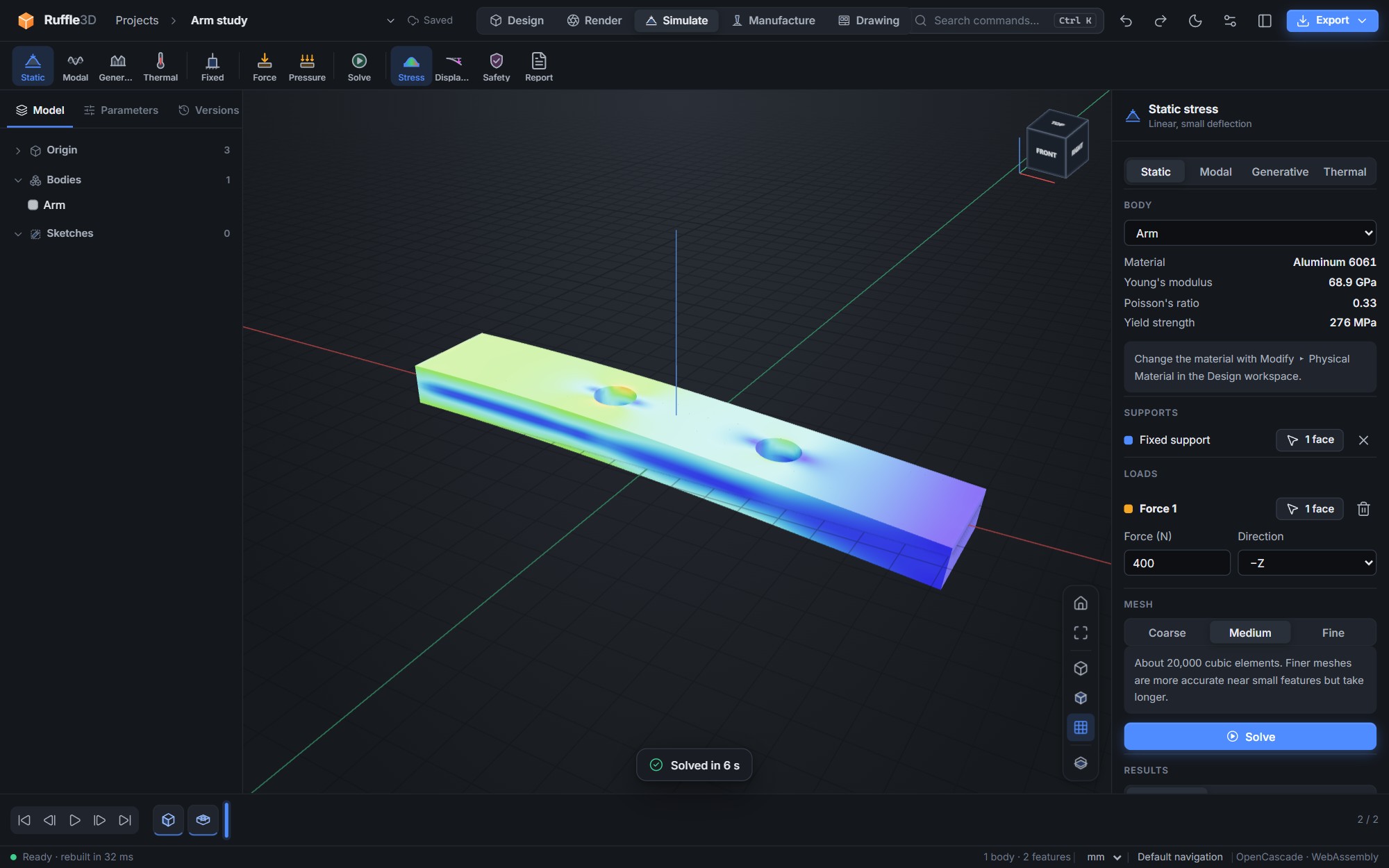
- Stress shows von Mises stress in MPa. Red areas carry the most load.
- Displacement shows how far each point moves.
- Safety shows the material strength divided by the stress. Red is below 1, which means the part will yield, or crack if the material is brittle. Blue is 4 or more.
- Deformed shape shows the part bent by its loads: at true scale, or exaggerated so small movements are visible.
The panel lists the peak stress, the stress at the supports, the largest displacement and the lowest safety factor. Report saves an HTML report with a picture of the result, the material, loads, mesh and solver details.
Natural frequencies
Choose Modal, add the fixed supports (loads aren't needed), pick how many modes you want and choose Solve. The panel lists each mode's frequency and the direction it mainly moves in. Click a mode to show it, and choose Animate to watch it vibrate. The colours show how far each point moves; mode shapes are scaled to fit, so only their pattern matters.
Keep the lowest frequency well away from the vibrations the part sees in use, such as a motor's running speed or a fan's blade-pass frequency, to avoid resonance. Stiffer or lighter designs have higher frequencies. For a steel cantilever, Ruffle3D's first frequency comes within 1% of beam theory.
Generative design
Choose Generative, add the supports and loads, and set how much of the material to keep. Generate then repeatedly solves the part and moves material to where it carries the most load, which is known as topology optimisation. Faces with supports and loads always keep their material. A coarse study usually takes about a minute.
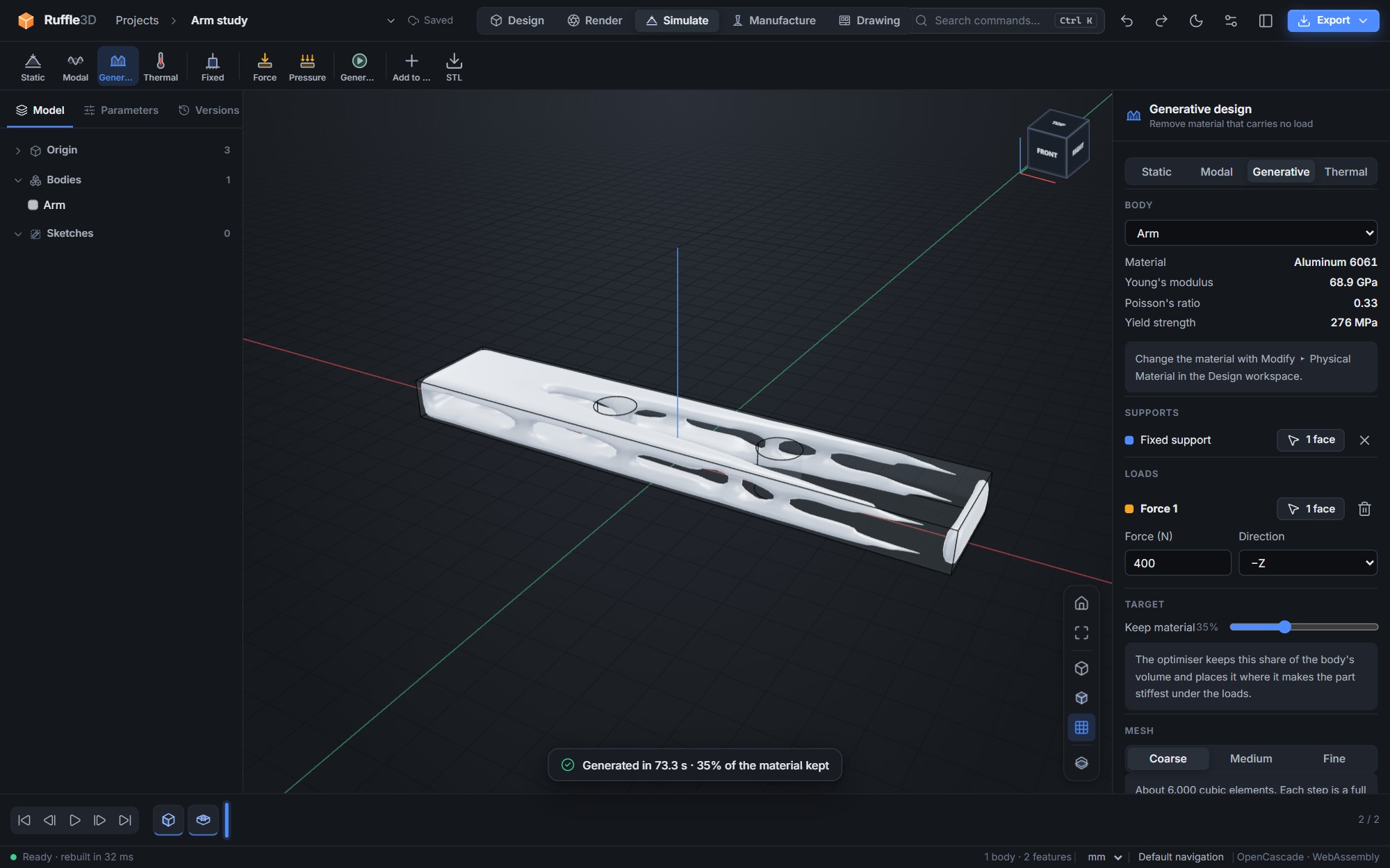
The result appears over a faint copy of the original part, with the share of material kept and how much of the full part's stiffness it keeps. Choose Add to model to add it as a body you can render, measure, simulate or 3D print, or STL to download it. The shape is a guide: most designers model a clean, manufacturable version over it.
Buckling
The Buckling study finds the load at which a slender part, such as a column, strut or thin wall, buckles sideways under the supports and loads you set up. It reports a buckling safety factor: the number you multiply your loads by to make the part buckle, with the critical load in newtons. Select a mode to see its buckled shape, and animate it. This is linear (eigenvalue) buckling: checked against Euler's formula for a steel column, the result agrees within 1%. Real parts with small imperfections usually buckle earlier, so keep a factor of 3 or more.
Yielding (plasticity)
In the Static study, turn on Material yielding to model metals and plastics above their yield strength. The material follows a bilinear curve: elastic up to the yield strength, then a small hardening slope. The stress is capped near the yield strength, the deflection grows where material yields, and the Plastic view shows the permanent strain. The panel shows how much material yielded and the deflection a purely elastic analysis would give. When the loads pass the part's collapse load, the result says so. The model assumes the load increases steadily (no unloading or cycling).
Thermal
Choose Thermal and add thermal loads from the toolbar:
- Temperature holds faces at a fixed temperature, such as a part bolted to a large cold frame.
- Heat puts a power in watts in through faces, such as a chip, an LED or a motor.
- Convection cools faces to the surrounding air or fluid. Set the film coefficient h and the ambient temperature. Typical values are 5–10 W/m²·K for still air, 25–100 with a fan, and 500 or more for flowing water.
Turn on Transient to see how temperatures change over time instead: set a starting temperature, a duration and a number of time steps. Drag the Time slider to see the part at any moment; a chart shows the highest, average and lowest temperature over the run. Heat capacity comes from each material's density and specific heat. Checked against the exact solution for a block cooling by convection, the result agrees within 0.5%.
Without Transient, the result is the steady state: the temperatures the part reaches after running for a long time. The panel shows the highest and lowest temperatures, the heat going in, and the heat leaving through fixed-temperature faces; the rest leaves by convection. Each material has a thermal conductivity, which you set with its physical material. Radiation and contact resistance between parts are not included. Checked against hand calculations for a bar and a convection-cooled plate, the results agree to within 1%.
Accuracy and limits
For a cantilevered steel beam, Ruffle3D's deflection and bending stress come within a few percent of textbook beam theory. Keep these points in mind:
- Deflections are assumed small. Static stress is linear and elastic unless you turn on yielding, which assumes steadily increasing loads. Buckling is linear (eigenvalue) buckling. Contact between parts, radiation, and the size of vibrations under a forcing load (only the natural frequencies and mode shapes) are not modelled.
- Stress at a sharp inside corner, or at the edge of a fixed face, rises as the mesh gets finer, because in theory it is infinite there. That is why the panel shows the peak stress away from the supports separately. Add fillets to corners where stress matters.
- Wood and fibre composites are treated as if they had the same properties in every direction.
- Use the results to compare designs and find weak spots, and confirm critical parts by testing.