Sketching and modelling
Sketches
Start a sketch with K and click an origin plane, a construction plane or any flat face. Sketches attached to faces follow the face when the model changes.
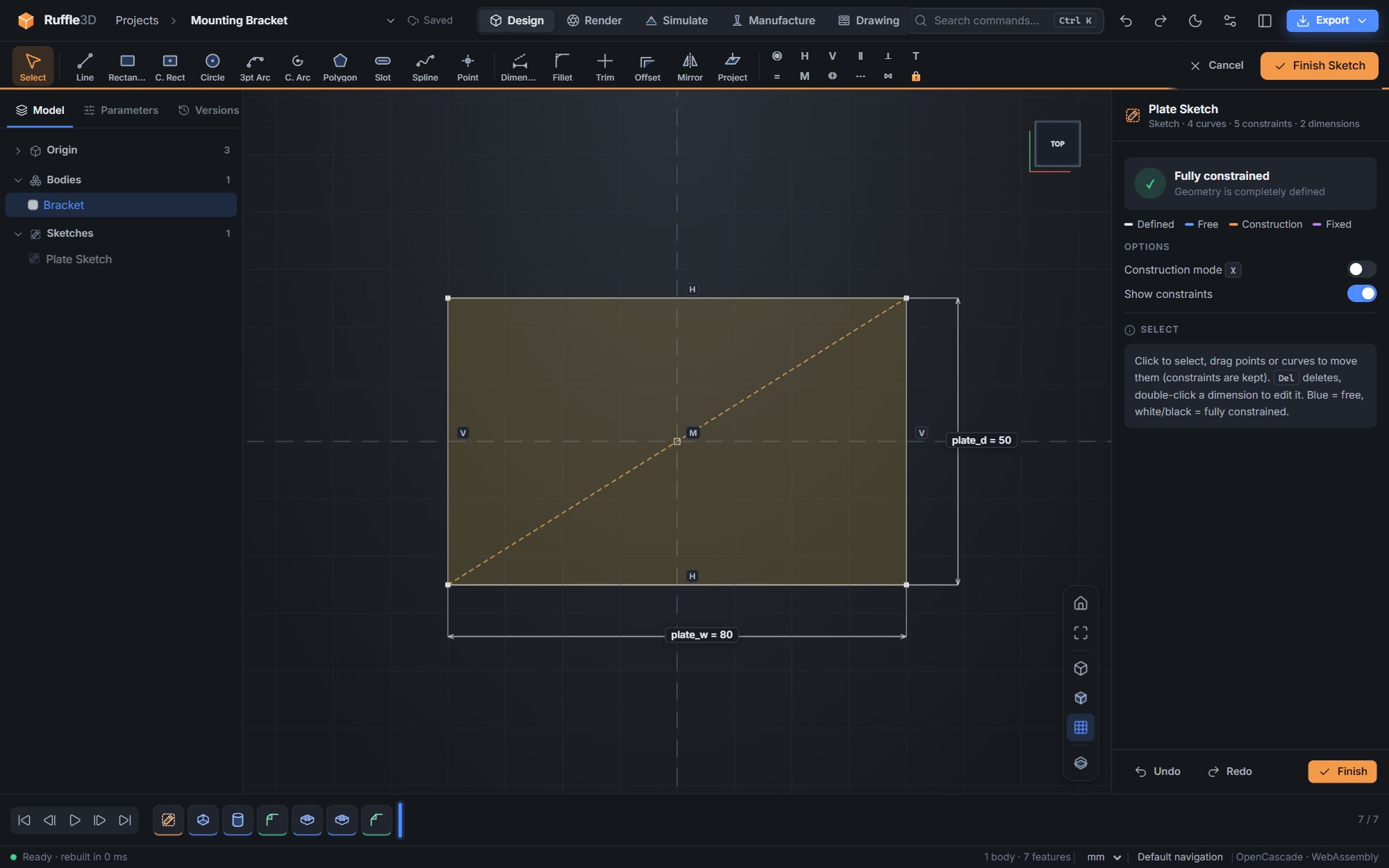
While you draw, Ruffle3D adds horizontal, vertical, coincident and midpoint constraints automatically. To give an exact size, type a number while a line or circle is being drawn. Construction geometry (X) is drawn dashed and is not used for profiles.
Trim removes the piece of a curve between the nearest crossings, and Offset makes a parallel copy toward the side you click. Both work on lines, arcs, circles and splines. A trimmed or offset spline is refitted through new points, so its shape near a cut can change very slightly.
Project copies edges of the model into the sketch as fixed reference geometry. Projections are associative: when the model changes, each projected edge is found again and moved, so dimensions and constraints that use it follow. If its edge is gone, the projection keeps its last position and the sketch shows a warning.
Closed regions become profiles. Overlapping curves split into separate regions, and loops inside other loops become holes. When you extrude or revolve, click the regions you want to use.
Constraints and dimensions
The colour of the geometry tells you its state: blue is free to move, white (black in the light theme) is fully defined, and red means the constraints conflict. The inspector shows how many degrees of freedom are left.
The Dimension tool (D) works on everything. Click a line for its length, two points for a distance, a circle for its diameter or two lines for the angle between them. Where you place the label decides whether a distance is horizontal or vertical. Double-click a dimension to change it. Values can be parameter expressions.
Solid features
| Feature | What it does |
|---|---|
| Extrude E | Pushes profiles into solids: one side, symmetric or two sides, with optional twist. Can create a new body, or join, cut or intersect an existing one. |
| Revolve | Spins profiles around a sketch axis or a world axis. |
| Sweep / Loft | Sweep moves a profile along a path sketch; Loft blends between two profiles. |
| Hole H | Simple, counterbored or countersunk holes on faces, to a depth or through all. |
| Fillet F / Chamfer | Rounds or bevels the selected edges. |
| Shell | Hollows a body to a wall thickness, removing the faces you pick. |
| Press Pull Q | Pushes or pulls flat faces by a distance. |
| Draft | Tapers faces against a neutral plane for moulding. |
| Split body | Cuts a body into two with a plane or face. |
| Patterns / Mirror | Rectangular and circular patterns of bodies; Path Pattern spreads copies along a sketch curve (evenly over its length, or a set distance apart) and can turn each copy to follow the curve; mirror about a plane. |
| Move / Scale M | Moves, rotates, copies or scales bodies. |
Threads and springs
Thread (Create ▸ more) adds a modelled ISO metric thread to a cylindrical face. Click a shaft for an external thread or a hole for an internal one; Ruffle3D detects which it is. Choose a size from M2 to M30, or a custom pitch. You can thread the whole face or a set length, change the start offset, flip the start end, and choose right or left hand. If the face diameter doesn't suit the size you chose, Ruffle3D warns you. For example, an M10 thread needs a Ø10 shaft, or a hole of about Ø8.5.
Coil creates a helical spring from a coil radius, pitch, number of turns and wire diameter.
Tapped holes
In the Hole tool, turn on Tapped and pick a thread size. The drill diameter is set from the ISO tap-drill size (for example Ø5 for M6). The thread is modelled to the depth you choose, or right through.
Text
Text (Create ▸ more) adds raised or engraved lettering for part numbers, logos and labels. Pick a plane or a flat face, type the text, and set the height, position, rotation and depth. Choose Emboss to add it on top of the face, or Engrave to cut it into the body. Press Shift Enter in the text box to start a second line.
The built-in Ruffle Engrave font is a single-stroke font made for machining and 3D printing. It has capital letters, numbers and common symbols, in thin, regular or bold strokes. To use another font, choose Load a font file in the Font list and pick a TTF or OTF file. The font is saved inside the project, so the text rebuilds on any computer. Check that the font's licence allows embedding.
Exploded views
Explode (Assemble) spreads the bodies of an assembly apart. Choose Radial to move parts away from the centre, or X, Y or Z to stack them along an axis: the largest part stays put and the others lift away from it in order, so parts inside a housing come out of the top. The model doesn't change. Turn on Use in the Render workspace, or use the Exploded view section of the Render panel, to capture images and turntable videos of the exploded assembly.
Canvas images
Insert ▸ Canvas puts a photo, sketch or blueprint on the XY, XZ or YZ plane so you can model over it. Set the width to a size you know from the image to calibrate it, then move, rotate, mirror or fade it. Canvases only appear in the Design workspace and are never part of the model.
Sheet metal
Sheet metal tools are in the Sheet Metal group of the Solid toolbar.
- Draw the outline of the flat plate in a sketch. Use straight lines for any edge that will get a flange.
- Choose Base, pick the profile, and set the thickness, the inside bend radius and the K-factor. The K-factor is where the neutral axis sits through the thickness: 0.44 suits most steel and aluminium bent in a press brake. Turn on Flip thickness side to grow the plate below the sketch.
- Choose Flange and click one or more straight outside edges of the plate. Set the length after the bend, the bend angle and the direction. Inset from corners stops the flange short of both corners, which leaves room for neighbouring flanges.
- Add holes or cut-outs with the normal tools: Hole, or an extrude set to Cut.
- Choose Flat to see the flat pattern. It lists every bend and the blank size, and Download DXF saves it for cutting.
The flat length of each bend is the bend allowance, θ × (R + K × T), where θ is the bend angle in radians, R the inside radius and T the thickness. Flanges start at the edge of the plate, so a 90° flange adds R + T to the outside size of the folded part.
Flanges can carry flanges: click the end edge or a side edge of a flange to fold a lip, a return or a side tab from it. The flat pattern unfolds every level. Each edge takes one flange.
Configurations
Configurations are named variants of one design, for example S, M and L. Open Insert ▸ Configurations, or choose Table in the Parameters tab, to edit a table: one row for each parameter, one column for each variant. Leave a cell empty to use the Default value. Switch the active configuration from the Parameters tab, or click the chip in the viewport. Export CSV and Import CSV move the table to and from a spreadsheet such as Excel: the first row is Parameter, Default and the configuration names. Importing updates the values, adds new configurations by name, and lists any parameters it didn't recognise. Export STEP for every configuration writes one file per variant.
The timeline
When you change a dimension or edit an earlier feature, later features find their faces and edges again from a fingerprint taken when you picked them (position, direction, size and shape), not just from where you clicked. If an edge or face has been split in two, fillets, chamfers, shells and drafts apply to all the pieces. If a reference really can't be found, the feature turns red and asks you to pick again.
Every feature appears in the timeline at the bottom of the window. Double-click a feature to edit it, or right-click to rename, suppress or delete it. Drag the marker to roll the model back and insert new features earlier in the history. Features that fail are shown in red, with the reason in the inspector. Features with warnings are amber.
Assemblies
An assembly is a design made of other projects. Save each part as its own project, then open a new project and choose Component (Assemble) to place them. Ruffle3D keeps a copy of each part in the assembly, so it still opens if the part's project changes or is deleted. Put the same part in several times and the bill of materials lists it once with a quantity.
Mate fits parts together. Click a face on each part and choose the mate type:
- Mate: flat faces against each other, with an optional offset (gap).
- Flush: flat faces level and pointing the same way.
- Concentric: two round faces on one axis, such as a pin in a hole. A pair of round faces gets this type automatically.
- Distance: parallel flat faces a set distance apart, measured out from the first face (use a negative distance for the other side).
- Parallel, Perpendicular and Angle: faces or axes at a set angle.
- Contact: a flat face rests on another. The part can lift off but can't sink into it.
- Gear: two round faces turn together at a ratio (the first gear's teeth ÷ the second's). They turn in opposite directions unless you choose Same direction for a belt or chain. Add concentric mates to hold each gear on its shaft.
- Rack and pinion: pick a round face on the pinion, then the flat end face of the rack. Turning the pinion slides the rack by pitch radius × the angle turned.
- Limits: turn on Range for a Distance or Angle mate to give a minimum and maximum instead of one value. The part can then slide or swing freely between the end stops, and dragging it stops at the ends.
All mates are solved together after every change. The first component is grounded (fixed) unless you ground another in the Assembly panel; parts with no mates stay where you put them. The panel shows each mate's status and how many degrees of freedom are left. When a mate can't be satisfied together with the mates added before it, it turns red and the others stay satisfied. In the Assembly panel you can drag a part with the mouse: it moves only in the directions its mates leave free. When a part's project changes, the panel offers Update; mates are kept, because their faces are stored in the part's own coordinates.
Turn on Check collisions in the Assembly panel to list parts that overlap after each change, with the overlap volume.
Joint (J) positions one body against another. Mate a face to a face, or a pin to a hole. Revolute and slider joints can be animated. Interference lists the volume where bodies overlap and shows it in red.
Inspecting parts
- Measure (I): lengths, radii and areas, plus the distance and angle between two picks.
- Section: a live section plane through the model, with capped cuts.
- Properties: select a body for its mass, volume, area, centre of mass and moments of inertia: the principal moments and axes and the full inertia tensor about the centre of mass, in kg·mm², from the body's material.
- Bill of materials (Inspect ▸ more): every body's material, volume, mass, area and size. You can copy it or download it as CSV.
- Wall thickness (Inspect ▸ more): colours the model by how thick the material is under each point of the surface, measured straight into the part. Set a minimum wall: anything thinner turns red, and the panel shows the thinnest wall and how much of the surface is below the minimum. Use it for moulded and printed parts, and to find thick sections that could sink or warp.
- 3D print check (Inspect ▸ more): choose the build direction and the overhang limit. Faces that need support are red, borderline faces amber and the face on the build plate blue. The panel lists each body's size, whether it fits the build volume you pick, whether its mesh is watertight, its overhang area, and an estimate of the filament it needs.
- Draft analysis, zebra and isophotes work on solids as well as surfaces. See Surfacing.